From BIM Model to Slab: How Robotic Layout Works
Robotic layout (also called automated layout) takes a coordinated BIM or CAD model and prints it full-scale on the slab. The model goes from Revit or AutoCAD, through the Dusty plugin, to the Dusty Portal, and the FieldPrinter prints every line, point, and label where the model says it goes. The field builds from the model instead of re-interpreting drawings by hand.
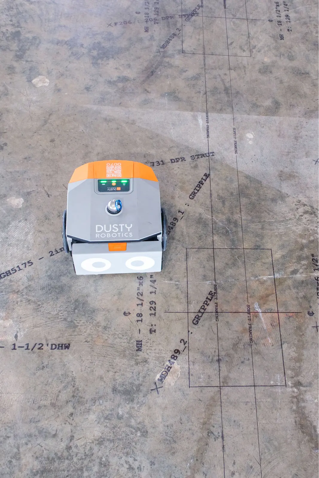
A Dusty FieldPrinter prints framing layout and text directly on the slab, around pipe stub-ups and penetrations.
How does layout get from a BIM model to the slab?
Automated layout runs in four steps:
- Prepare the model. The design or VDC team builds the layout in Revit or AutoCAD and coordinates it so each trade's lines are correct and free of clashes.
- Send it through the plugin. The Dusty plugin pushes the layout from Revit or AutoCAD to the Dusty Portal, where it's managed and queued to print.
- Set control. On the slab, the FieldPrinter stations itself against the jobsite control points using Dusty's laser tracker for reference.
- Print. The robot drives the slab and prints the layout in ink at full 1:1 scale.
From there the field reads printed lines and text off the floor instead of measuring from drawings. The model becomes the thing the crew builds from, which is the whole point of robotic layout.
What software and hardware make it work?
The software side is the Revit and AutoCAD plugins plus the Dusty Portal, where the layout file lives and gets prepared. The hardware side is the FieldPrinter, which prints on the slab, and Dusty's laser tracker, which sets control. An iPad app drives the robot in the field. Together they form the path from a coordinated model to a printed layout with no manual transcription in between.
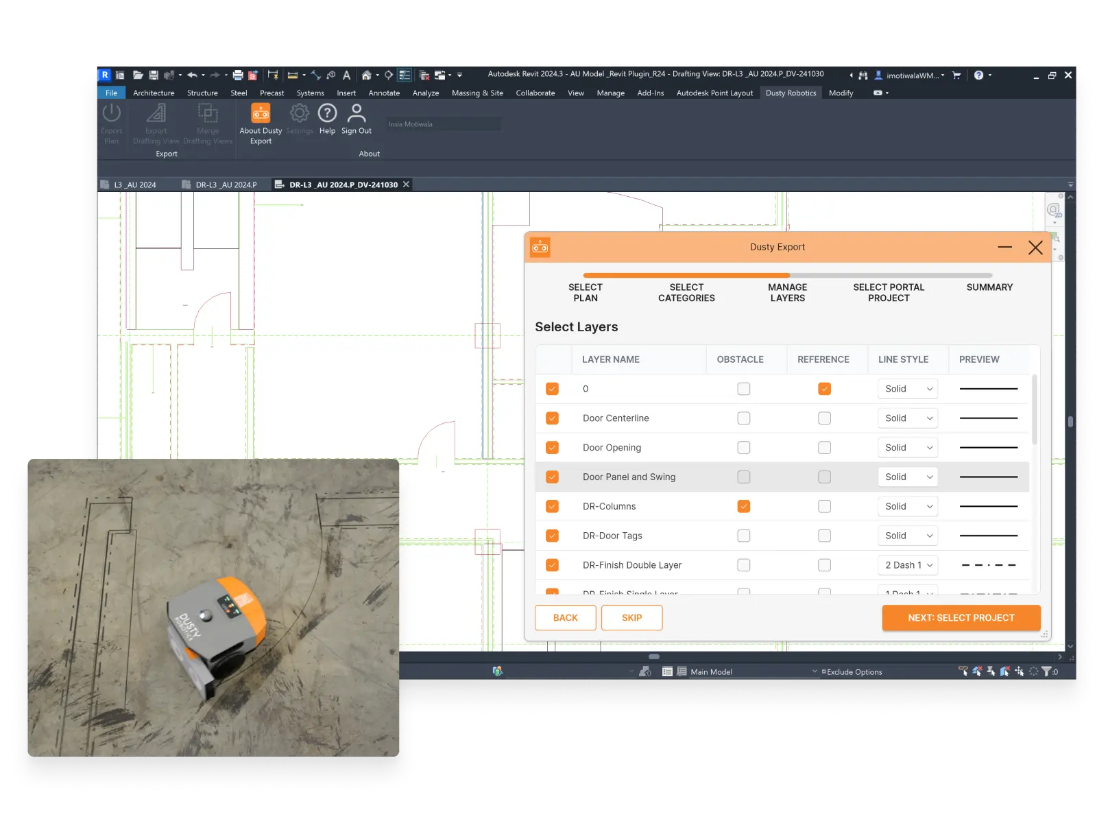
The Revit/AutoCAD export plugin sends selected layers from the model to the Dusty Portal.
Who does what?
- VDC Manager validates the coordinated model and signs off that it's ready to print.
- VDC Engineer manages the file in the Portal and preps it for the field.
- Operator runs the FieldPrinter on the slab.
No survey crew is required to operate the robot, which is part of why automated layout fits inside a VDC-led workflow rather than a separate survey scope.
What can robotic layout actually print?
Automated layout prints the same information a crew would mark by hand, and more of it, in one pass:
- Wall lines and partition layout.
- Penetrations and openings for doors, MEP, and equipment.
- Control points and reference marks.
- Text and labels so crews can read what each line is without a drawing.
Because the data comes from one coordinated model, robotic layout can also print several trades at once rather than one trade at a time. That multi-trade pass is where the time savings compound.
The FieldPrinter prints a range of point symbols, from control points to MEP markers.
What makes a model "layout-ready"?
The output is only as good as the model, so the prep matters. A layout-ready model is fully coordinated, with its control points defined and its layout content mapped to the right lines and labels for each trade. Getting this right up front is the work; once the model is clean, the print itself is fast. This is why automated layout rewards teams that invest in coordination: the field speed comes from the model discipline, not from the robot moving faster.
How accurate is it, and how is it verified?
The FieldPrinter prints at 1/16-inch accuracy. Before it prints, it compares measured control against the model, so the team can confirm the slab matches the model and catch a control problem before any layout goes down. That verification step is the difference between trusting the printed layout and re-checking it by hand.
Your browser does not support the video tag.
A printed layout with a Portal published-layers overlay; a slab core lands exactly on the printed mark.
Where does robotic layout fit in the schedule?
Layout sits between a ready slab and the trades who build on it, so it often lands on the critical path. Because automated layout collapses what used to be days of sequential, trade-by-trade marking into a single coordinated pass, it shortens that critical-path step and lets trades start sooner. Getting the model coordinated early is what makes the field pass quick.
How is this different from manual layout and total stations?
Manual layout re-creates the drawings on the slab with tape and chalk, one trade at a time. A total station marks individual points one at a time and still needs an operator reading the drawings between points. Robotic layout prints the full coordinated model for every trade in one pass.
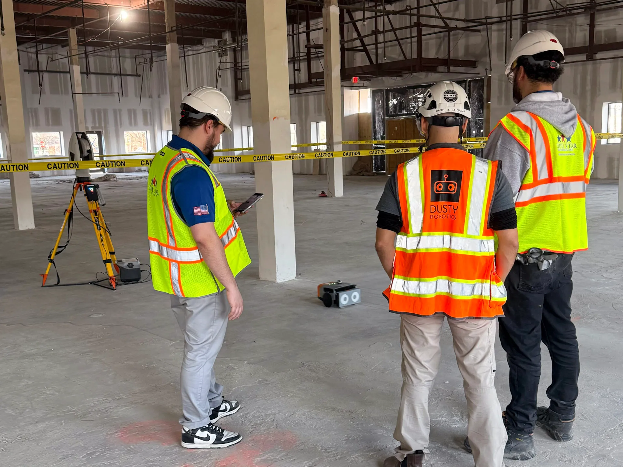
The FieldPrinter sets control with Dusty's laser tracker, not a total station.
What this looks like on a real project
"Kaiser wants us to maximize model-based workflows. With Dusty, we can show them that we're executing the model in the field, which gives us a huge competitive advantage."
— Glen (Sully) Sullivan, VDC Manager, McCarthy
Key facts about BIM to Field
- The workflow runs Revit/AutoCAD to the Dusty plugin to the Dusty Portal to the FieldPrinter to the slab.
- Roles: the VDC Manager validates the model and the VDC Engineer preps the Portal file, then an operator runs the robot.
- Robotic layout prints wall lines, penetrations, control points, and text, for multiple trades in one pass.
- Prints at 1/16-inch accuracy; control is set with Dusty's laser tracker, not a total station.
- Measured-vs-modeled control is checked before printing.
- 300M+ sq ft printed and 125+ robots printing daily as of 2026.
Frequently asked questions
What software do I need to run robotic layout?
The Autodesk Revit or Autodesk AutoCAD plugin to export the layout, and the Dusty Portal to manage the file. The FieldPrinter and its iPad app handle the field side.
Does it work with both Autodesk Revit and AutoCAD?
Yes. The plugin supports both, so the automated layout comes straight from whichever tool the team models in.
Who runs the robot, and do I need a surveyor?
No survey crew is required. A VDC engineer prepares the file and an operator runs the robot; control is set with Dusty's laser tracker.
How do I know the printed layout matches the model?
The system compares measured control against the model before printing, so the team verifies the match before any line goes on the slab.
What does the robot print besides wall lines?
Penetrations and openings, control points, and text labels, for multiple trades from one coordinated file.
How is robotic layout different from automated layout?
In this case, they are the same thing. "Robotic layout" and "automated layout" both describe a robot printing a coordinated model onto the slab; this article uses the terms interchangeably. Some people also use Robotic layout to include Robotic Total Stations (RTS) systems as well.