
How Do You Lay Out Equipment Pads and Anchor Bolts Accurately?
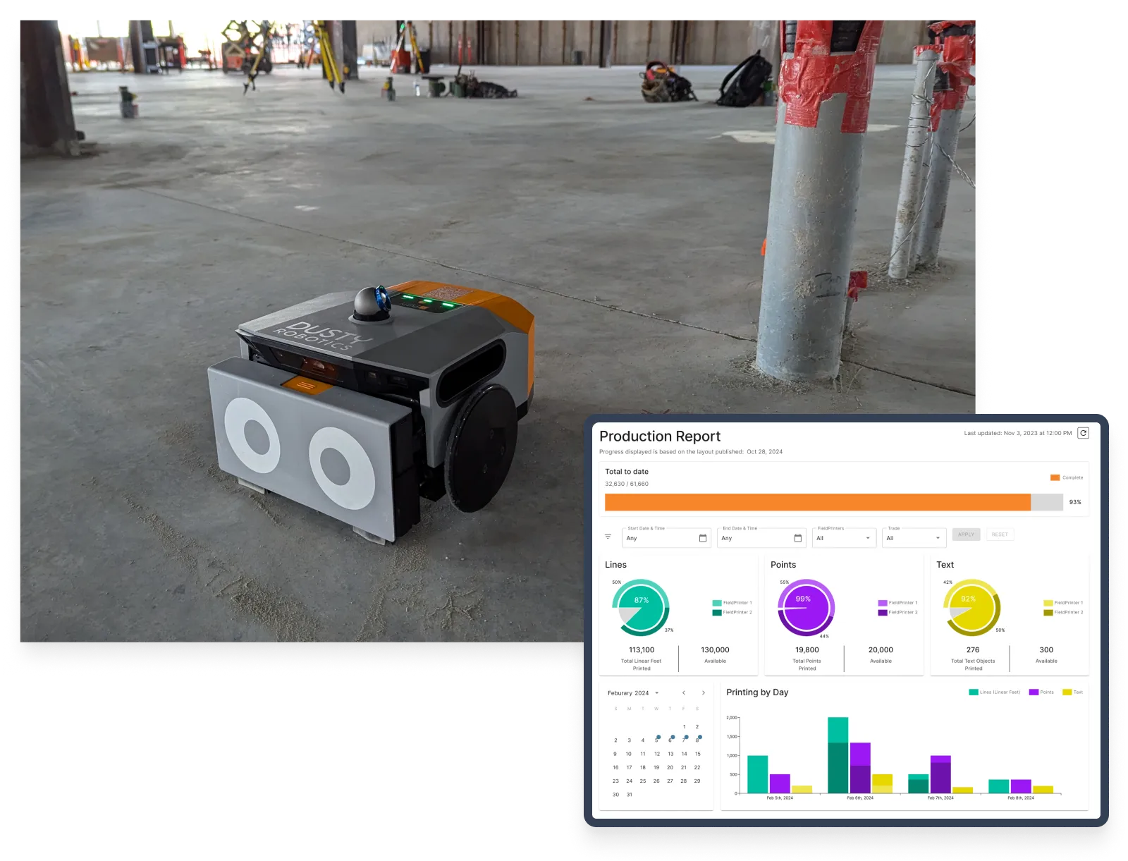
Equipment pads and anchor bolts get laid out from the coordinated model, either by hand from 2D sheets or by printing the model full-scale onto the slab. The tolerance and installation instructions are what makes the choice matter: you cannot move a bolted machine after it is set, and every time installers put down their tools to look at installation instructions is wasted time. Automated layout prints anchor patterns at 1/16″ accuracy, and one contractor held that figure across an entire jobsite, all while printing full installation instructions and part details on the slab.
Why is anchor bolt layout unforgiving?
Because the error becomes permanent the moment concrete cures and the machine lands on it.
A drifted wall line gets absorbed by finishes. A drifted anchor bolt pattern does not. Correcting one after the equipment arrives means a crane, downtime, and schedule slippage measured in weeks. Long-lead machinery makes it worse, because the rework window opens exactly when the procurement window has already closed.
The cost shows up in the benchmarking data. A 2001 Construction Industry Institute study put mean field rework above 3% of construction-phase cost on heavy industrial projects, and CII's 2011 rework guidance widened the range to 2% to 20% of contract value depending on the job. Those figures are old, and they are the ones the industry still cites.
How is equipment pad layout done today?
The conventional process starts with a survey crew setting control tied to the structural grid, then a layout crew working outward from those points with tape measures and chalk lines, reading dimensions off 2D sheets printed from the coordinated model.
Two problems compound. Each hand-transferred measurement carries a small error, and on a floor with hundreds of pads and embeds those errors accumulate across the span. Meanwhile the crew is re-deriving 3D coordination data from flat printouts, so a resolved clash in the model can reappear as a field conflict. On an active industrial floor the reference points themselves degrade as foot traffic smears marks and staged material covers control.
How does automated layout handle anchor bolt patterns?
It prints the pattern directly from the coordinated model at full scale, so the marks on the slab are the model rather than an interpretation of it.
The FieldPrinter reads the coordinated Revit or AutoCAD file through Dusty's plugin, and prints at 1/16″ accuracy and 600 DPI with one operator running it. Bolt patterns, pad outlines, embeds and alignment references all come off the same file.
Alston Construction had a job where that tolerance was the whole requirement.
“Our client designed an amazing new system with these robots moving up to 25 miles per hour. But in order for it to work, the offset between rails couldn't be more than 1/16th of an inch. So this construction required high quality checks that were costing us time. With Dusty, we could maintain a 16th of an inch precision across the entire jobsite.”
— Rickey Molina, VDC Director, Alston Construction
What else goes on the slab besides the bolt points?
Most of what the installer would otherwise stop and look up. A chalk line tells a crew where a machine goes. The same print can also carry how to orient it, which fasteners to use, and how tight to torque them.
Five mechanisms do that work, and they combine on one pass:
- Point styles. FieldPrinter 2 prints layout points as distinct symbols rather than identical dots. Nine standard icons, from a plus to a crosshair, get assigned per layer in Dusty Portal, so a crew can see at a glance which points belong to which trade or system. Dusty auto-generates a legend mapping each layer name to its symbol, which either prints onto the layout or downloads as a PDF to post on-site. Details are in Introducing Point Styles.
- Point rotation. Points and their text labels can be rotated by layer, which gives a second visual channel for telling one discipline's points from another's.
- Text labels. Any text in the model prints, in any language. On industrial work that means part numbers, footplate IDs, torque specs, and assembly references sitting next to the point they describe.
- Enriched line styles. Text can ride inside the line itself, so a run reads CONDUIT or carries its own offset dimension without a separate callout.
- QR codes. Codes print as their own layer and resolve to any URL the engineering team specifies, which is how a slab starts working as a reference library rather than a set of marks.
Printed point styles with an auto-generated legend, so each trade can find its own points at a glance.
The practical effect is that the installer stops walking back to the drawing table. That, rather than printing speed, is what moves installation throughput.
Laying out machine bases on an upcoming buildout?
Who decides what information goes on the floor?
Whoever owns the engineering. On Bouma Corporation's factory work the split is deliberate: the facility's engineering team preps the CAD file with what their installers need, and Bouma makes sure it prints correctly.
“We ask them to prep the file the way they'd like to see it. They own the content; we make sure it prints right. [We tell them to] think about anything that would help your installer. You want to give the most critical, highest-value information.”


That division keeps liability where it belongs, and it settles the question of who is accountable for a wrong dimension on the floor.
There is a discipline to it. More information is not automatically better, because a cluttered layout is harder to read than a sparse one. The useful test is whether a given mark saves the installer a trip to the plans.
What happens when the slab doesn't match the model?
The robot shows you the discrepancy before it prints, which is the part of the workflow that matters most on a brownfield floor.
Stationing uses a minimum of three control points measured with Dusty's Laser Tracker at sub-1/32″ accuracy, and no survey experience is required. After scanning, Dusty displays a comparison of measured against modeled control point positions. An operator can diagnose poor field control and adjust the print file alignment before ink goes down, instead of finding out that an older slab does not match its drawings after the layout is on the floor.
That comparison is also the verification record. On a conventional pass, checking the marks against the model is a second labor cycle after the marking is finished.
Can it print next to existing steel and equipment?
Yes. The FieldPrinter prints within 0.825″ in front of and 1.25″ alongside any wall, obstacle, or slab edge, which covers anchor patterns tight against existing structure without hand-finishing the last few inches.
Industrial floors are rarely clear. AI-driven computer vision routes the robot around common jobsite obstacles without operator intervention, and obstacles that were never in the model can be scanned into the print job on the spot. It also prints in zones a total station cannot see, so working behind existing steel does not mean repositioning survey equipment.
What does this look like on a real industrial project?
The pattern worth copying is that throughput gains follow information density, not print speed.
Bouma Corporation, a West Michigan contractor, built an industrial layout service on Dusty and has completed roughly two dozen industrial layout jobs across automotive, data center, and rack manufacturing facilities. Machine positions, bolt patterns, torque specs and QR-coded work instructions go straight onto the factory floor. Where a facility asks for a code beside every unit, that code resolves to a URL the factory's own engineers control, so updating the documentation behind it never means reprinting the slab.
The FieldPrinter prints a scannable QR code beside hanger and strut point labels.
At a rack manufacturing facility in Middlebury, Indiana, that approach tripled the install rate. The facility's crews had been laying out one manufacturing unit and installing it in a day. Bouma printed three units in a day and the crews installed all three, which is the clearest available demonstration that the constraint was never how fast the marks went down.

Machine positions, bolt patterns and install detail printed straight onto the factory floor.
“They typically lay out one unit and install it in a day. I got three units laid out in a day, and they were able to install all three — not because I completed three, but because the information on the floor was clear enough that their guys could just set the unit down, put it where it needed to go, and move to the next one.”
The install crews stopped running a search-and-verify cycle between units. Bouma now runs Dusty on 90% of projects across the company.
The same shift shows up differently where accuracy rather than instruction is the binding constraint. On Alston's robotic distribution center, previous jobs took roughly 15 days for four people. With Dusty it took five days with a single operator, a 67% reduction in schedule and a 92% reduction in person-days. Both outcomes come from the same move: put complete, trustworthy information at the point of work and the trades stop waiting on verification.
Key facts
| Measure | Figure |
|---|---|
| Print accuracy | 1/16″ at 600 DPI |
| Point styles | Nine standard symbols assigned per layer, plus point rotation and an auto-generated legend |
| What else prints | Part numbers, footplate IDs, torque specs, assembly references, enriched line styles, QR codes |
| Control points required | Minimum 3, measured at sub-1/32″ accuracy |
| Survey experience needed | None |
| Closest print to an obstacle | 0.825″ in front, 1.25″ alongside |
| Alignment check | Measured against modeled control points, shown before printing |
| Alston, robotic distribution center | 1/16″ held jobsite-wide; 15 days × 4 people to 5 days × 1 operator |
| Bouma, Middlebury IN rack facility | Install rate from one unit per day to three |
| Bouma overall | ~two dozen industrial jobs, 3X faster installation, Dusty on 90% of company projects |
| Heavy industrial field rework (CII, 2001) | Mean above 3% of construction-phase cost |
Frequently asked questions: equipment pad and anchor bolt layout
What tolerance does anchor bolt layout need to hold?
Anchor bolt tolerance depends on the equipment, and the OEM base drawing is the governing document rather than any construction standard. The practical answer is that the layout should be tighter than whatever the machine tolerates, so layout stops being the weak link. In practice, the FieldPrinter prints at 1/16″ accuracy and 600 DPI. Where the requirement is unusually tight, Alston's rail-offset case is the useful reference: the system could not tolerate more than 1/16″ between rails, and that figure held across the entire jobsite.
What information can you print on the floor besides layout lines?
Dusty's FieldPrinter 2 prints point symbols, rotated point labels, and any text that exists in the model, which on industrial work usually means part numbers, footplate IDs, torque specs, and assembly references. Line styles can carry text inside the line itself, and QR codes print as a separate layer resolving to whatever URL the engineering team specifies. Bouma prints machine positions, bolt patterns, torque specs, and QR-coded work instructions on factory floors as standard practice. The constraint is legibility rather than capability: a cluttered slab is harder to use than a sparse one.
Who decides what information gets printed on the floor?
The team that owns the engineering. On Bouma Corporation's factory work the facility's own engineers prep the CAD file with what their installers need, and Bouma verifies it will print correctly on the FieldPrinter before showing up to print it. That split matters for liability, because the layout provider never takes on the engineering decisions inside the file. It also produces better output, since the people who know the equipment are the ones deciding what information the installer sees.
Can a layout robot print embeds and pads before the pour?
Printing happens on a cured slab, so pre-pour embed work is a different problem. The FieldPrinter handles layout on the finished slab for anchor patterns, pad outlines, machine positions, and alignment references, plus the labels and QR codes that tell the crew what each mark is. On retrofit and brownfield work, the measured-against-modeled control point comparison is what reconciles the print with a slab that no longer matches its drawings.
How does a layout robot stay accurate on an older, uneven slab?
The FieldPrinter stations against the physical building rather than assuming the model is correct. A minimum of three control points get measured with Dusty's Laser Tracker at sub-1/32″ accuracy, then Dusty shows the operator how the measured positions compare with the modeled ones. Poor field control becomes visible before printing rather than after, and the print file alignment can be adjusted to the slab that actually exists. No survey experience is required to run the process.
Who operates a layout robot on an industrial project?
One operator runs the FieldPrinter from a tablet app. The role does not require a robotics background or survey training, which is the point when survey talent is the scarce resource on a plant buildout. Bouma built an entire industrial layout service on this basis and now runs Dusty on 90% of the company's projects. For contractors who would rather not run it in-house, Dusty's Certified Partner Program delivers the same FieldPrinter and the same accuracy as Layout-as-a-Service.